Boundary vs. Mixed Lubrication: A Regime-First Framework for Lubricant Selection
Your oil choice depends on which lubrication regime your component spends most of its time in. Boundary and mixed lubrication are not failure modes — they are normal, predictable operating zones on the Stribeck curve, and the key to specifying the right lubricant is identifying which regime your equipment actually operates in using measurable data: lambda ratio, speed, load, temperature, and viscosity.
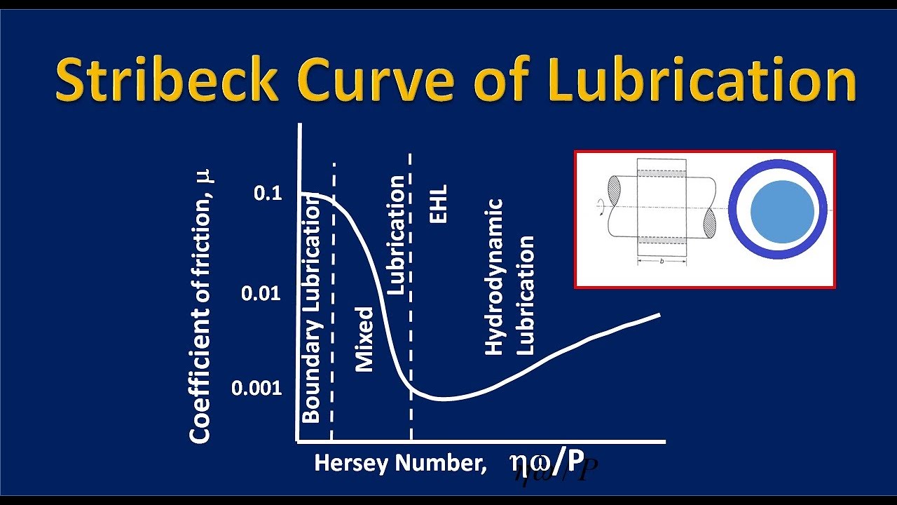
The Stribeck curve plots friction coefficient against the Hersey number (viscosity × speed / load), producing four zones: boundary, mixed, elastohydrodynamic (EHD), and hydrodynamic. At the lowest Hersey numbers — low speed, high load, or low viscosity — asperities contact and friction is governed by additive film chemistry. As speed rises or load falls, the curve enters mixed lubrication, where asperity contact and partial fluid film coexist. At higher Hersey numbers, EHD and hydrodynamic regimes develop full fluid films, and friction is determined by viscous shear.
This curve is your diagnostic anchor. Locate your component on it, and lubricant selection becomes a regime-matching exercise rather than a guess based on viscosity grade alone.
Boundary Lubrication: When Additive Chemistry Replaces Fluid Film
Boundary lubrication occurs when the lambda ratio (film thickness divided by composite surface roughness) falls below 1, meaning no continuous fluid film separates the surfaces. Load is carried by asperity contact and by anti-wear and friction modifier additives that form sacrificial or reactive films on metal surfaces.
Base oil viscosity has minimal effect on load-carrying capacity in this regime; additive chemistry dominates friction and wear control. ZDDP, molybdenum compounds, and other anti-wear or friction modifier additives are the primary performance levers. Automotive examples include cam-follower contacts during start-up, valve train at low speed, and gear teeth under high load at low speed.
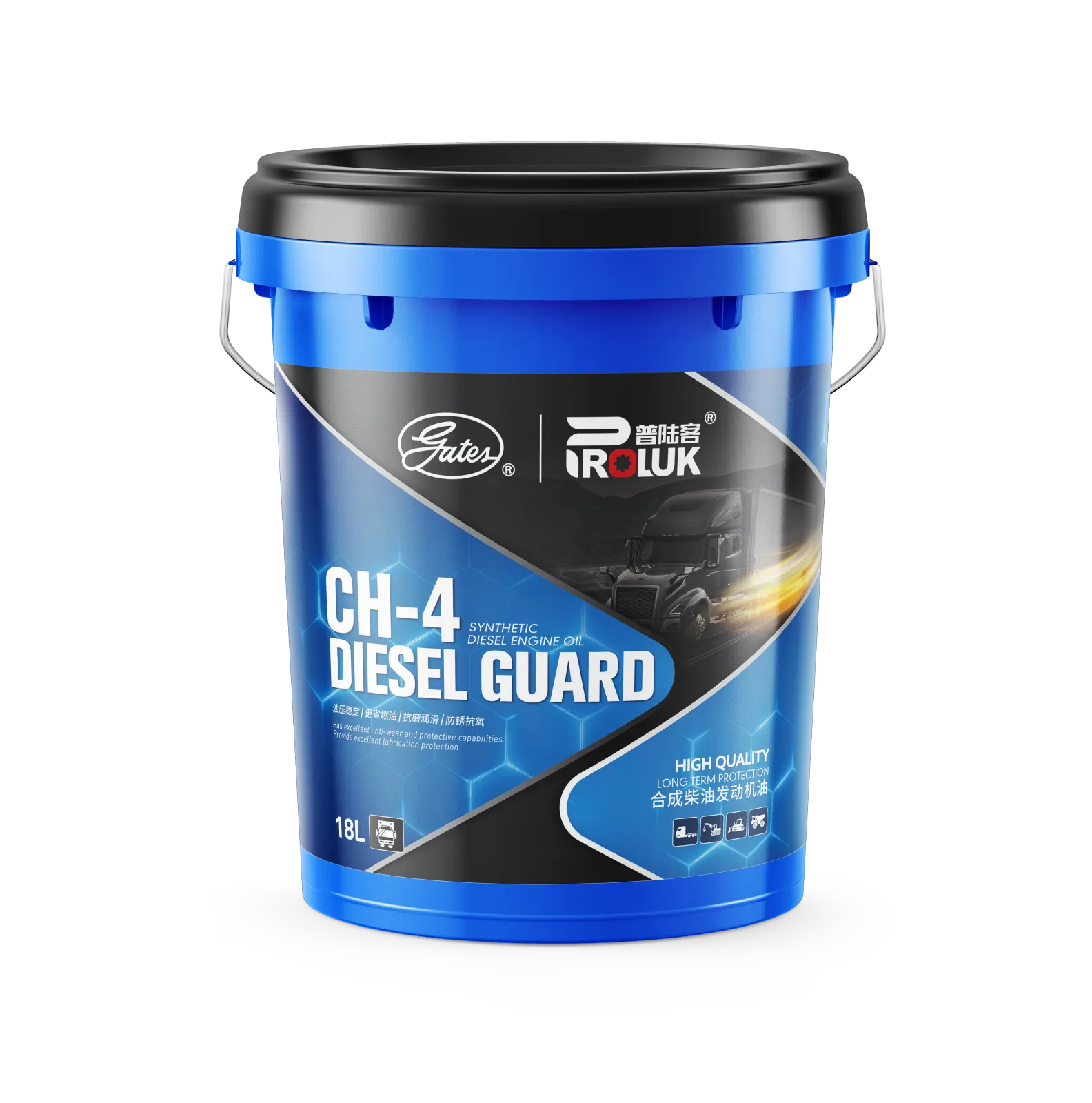
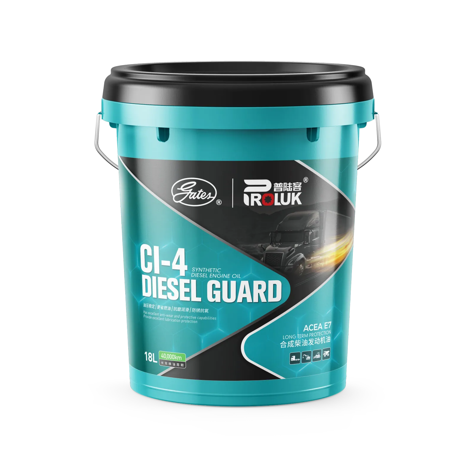
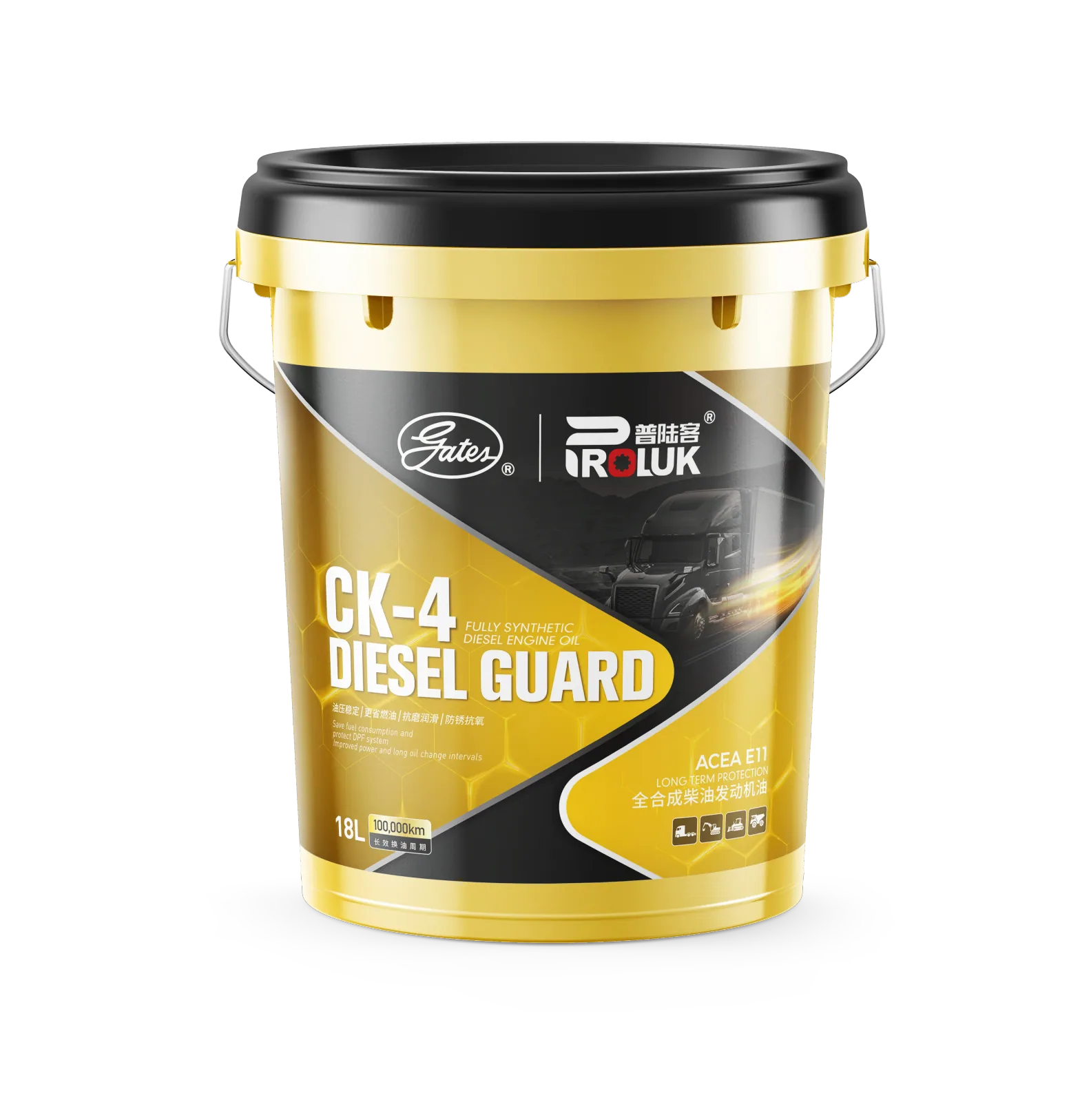
If your equipment operates in boundary lubrication, specifying a higher viscosity base oil will not solve wear. You need a lubricant with a robust anti-wear additive package. For heavy-duty diesel engines, oils in API CH-4, CI-4, or CK-4 categories are formulated with anti-wear additive packages intended for boundary conditions; actual treat rates vary by marketer and should be confirmed against the specific product data sheet or OEM specification.
Decision rule: If your calculated lambda ratio falls below 1, prioritize oils with high ZDDP levels and verify the additive package against the OEM specification for your component.
Mixed Lubrication: The Normal Transition Zone Most Equipment Lives In
Mixed lubrication occurs at lambda ratios between approximately 1 and 3, where both asperity contact and partial fluid film contribute to load support. It is a normal operating regime, not a failure mode. Friction in mixed lubrication is a weighted average of boundary and hydrodynamic contributions; both additive chemistry and base oil viscosity matter.
Mixed lubrication is normal during start-up, low-speed high-load operation, and transient conditions in engines, gearboxes, and transmissions. The goal is not to eliminate mixed lubrication but to ensure the lubricant formulation manages it without excessive wear or friction. A 15W-40 CI-4 engine oil, for example, is formulated to handle mixed lubrication in the valve train and cylinder liner during normal driving cycles.
Decision rule: If your calculated lambda ratio falls between 1 and 3, balance viscosity and additive treat rate — do not default to a higher viscosity grade without confirming that the additive package is adequate for the boundary contribution.
Quantitative Regime Transitions: Lambda Ratio Thresholds and What They Mean for Your Equipment
Lambda ratio (Λ) = minimum film thickness / composite RMS surface roughness. Typical thresholds: Λ < 1 = boundary, 1 < Λ < 3 = mixed, 3 < Λ < 5 = EHD, Λ > 5 = hydrodynamic.
Film thickness depends on speed, load, viscosity, and geometry; surface roughness depends on machining and wear. A practical method: estimate film thickness using Hamrock-Dowson equations or supplier data, measure or obtain surface roughness (Ra or Rq), then calculate Λ. Regime boundaries shift with temperature (viscosity change), load, and speed — so regime is dynamic, not fixed.
Worked Example: Lambda Ratio Calculation for a Gearbox Contact
Consider a gearbox operating at low speed and high load. Use the following inputs:
- Speed: 1.0 m/s entrainment velocity
- Load: 2.0 GPa maximum Hertzian contact pressure
- Viscosity: 0.05 Pa·s at operating temperature (approximately ISO VG 220 at 80°C)
- Composite RMS surface roughness (Rq): 0.4 µm
- Geometry: equivalent radius of curvature 0.02 m
Using the Hamrock-Dowson minimum film thickness equation for elliptical contacts, the estimated minimum film thickness is approximately 0.3 µm. The lambda ratio is then:
Λ = 0.3 µm / 0.4 µm = 0.75
A lambda ratio of 0.75 falls below 1, placing this contact in the boundary regime. The same gearbox at highway speed might reach Λ = 4 (EHD), demonstrating that regime is dynamic and depends on operating conditions.
Decision rule: Calculate Λ for your worst-case operating condition — typically low speed, high load, and high temperature. If Λ < 1, specify a lubricant with a robust anti-wear additive package. If 1 < Λ < 3, balance viscosity and additive treat rate. If Λ > 3, prioritize base oil viscosity and hydrodynamic efficiency.
How Lubricant Formulation Shifts Regime Boundaries: Base Oil Viscosity and Additive Chemistry
Higher base oil viscosity increases film thickness, shifting transitions to higher lambda ratios and expanding the hydrodynamic regime, but increases viscous drag. Anti-wear additives (e.g., ZDDP) and friction modifiers (e.g., MoDTC) reduce friction and wear in boundary and mixed regimes by forming protective films. Additive chemistry can extend the boundary lubrication limit, allowing equipment to operate safely at lower lambda ratios.
Formulation must balance boundary/mixed performance (additives) with hydrodynamic efficiency (viscosity) for the actual operating regime. A 75W-90 GL-5 gear oil uses high viscosity and EP additives to handle boundary/mixed conditions in differentials, while an ATF uses friction modifiers for clutch performance in mixed/EHD regimes.
Decision rule: When specifying a lubricant, match the additive package to the worst-case regime and the base oil viscosity to the typical operating regime. Do not use viscosity alone as a proxy for boundary performance.
Inferring Operating Regime from Real Machinery Data: Speed, Load, Temperature, Viscosity, and Lambda Ratio
Step 1: Measure or obtain operating speed, load, and temperature for the component. Step 2: Determine lubricant viscosity at operating temperature (from product data sheet or ASTM D341). Step 3: Estimate minimum film thickness using Hamrock-Dowson or supplier software. Step 4: Measure or obtain surface roughness (Ra or Rq) and calculate lambda ratio. Step 5: Map lambda ratio to regime and select lubricant accordingly.
For a commercial vehicle engine, you can use oil temperature and RPM to estimate viscosity, then compare with known surface roughness of cylinder liners to estimate Λ. If Λ < 1 during start-up, ensure your oil has sufficient anti-wear additives (e.g., CI-4 or CK-4).
Decision rule: If you cannot measure surface roughness directly, use published or OEM-supplied Ra/Rq values for the component. If lambda ratio is unavailable, use oil analysis trends and operating temperature as proxies for regime shifts.
Condition Monitoring for Regime Shifts: Oil Analysis, Temperature, Vibration, and Wear Debris
Regime shifts (e.g., from mixed to boundary) increase friction, temperature, and wear debris. These manifest in oil analysis, vibration, and temperature trends. Fixed drain intervals assume steady regime; they miss transient regime shifts caused by load changes, viscosity breakdown, or additive depletion.
Monitor these signals:
- Wear metals: Fe, Cu, and other wear debris in oil analysis
- Additive elements: ZDDP depletion (Zn, P), friction modifier depletion (Mo)
- Viscosity: Changes in kinematic viscosity at 40°C and 100°C
- Temperature: Rising sump or component temperatures at constant load
- Vibration: Changes in vibration signature indicating increased asperity contact
Thresholds are component-specific and must be set from a baseline. As a general rule, flag when Fe increases by more than 20 ppm over 100 hours at constant operating conditions, or when additive elements drop by more than 30% from baseline. Early detection of regime shift allows lubricant change or additive top-up before wear accelerates.
Decision rule: Establish a baseline for each component, then set alarm limits for wear metals, additive depletion, and temperature. Investigate any trend that exceeds the baseline by more than 20%.
Specifying Lubricants by Regime: Practical Examples for Engines, Gearboxes, and Transmissions
Engine start-up: boundary/mixed regime — specify oil with high anti-wear additive treat rate and appropriate viscosity for low-temperature pumpability. Gearbox at low speed high load: mixed/boundary — specify gear oil with high viscosity and EP additives. Transmission at steady speed: EHD/hydrodynamic — specify fluid with correct viscosity and friction modifiers for clutch performance.
Use lambda ratio calculations and condition monitoring to validate lubricant choice and adjust as operating conditions change. For heavy-duty diesel engines, API CK-4 10W-40 provides robust anti-wear for boundary conditions during start-up and mixed lubrication during load. For manual gearboxes, a 75W-90 GL-5 oil handles boundary/mixed in low-speed high-torque conditions. For automatic transmissions, a dedicated ATF with friction modifiers ensures proper clutch operation in mixed/EHD regimes.
Decision rule: Specify the lubricant for the worst-case regime the component experiences, not the average. Validate with lambda ratio calculations and condition monitoring.
FAQ
What lambda ratio should I target for a gearbox vs. an engine?
For a gearbox, target Λ > 1 for normal operation and Λ > 3 for high-speed efficiency. For an engine, target Λ > 1 during normal operation and accept Λ < 1 during start-up, provided the oil has sufficient anti-wear additives. The specific target depends on component geometry, surface finish, and OEM requirements.
Can I use a higher viscosity oil to fix boundary lubrication wear?
No. In boundary lubrication, base oil viscosity has minimal effect on load-carrying capacity. The correct fix is a lubricant with a robust anti-wear additive package, such as API CH-4, CI-4, or CK-4 oils for heavy-duty diesel engines. Confirm the additive package against the OEM specification.
How do I know which lubrication regime my equipment is in?
Calculate the lambda ratio: estimate minimum film thickness using Hamrock-Dowson equations or supplier data, measure surface roughness (Ra or Rq), then divide. Λ < 1 = boundary, 1 < Λ < 3 = mixed, 3 < Λ < 5 = EHD, Λ > 5 = hydrodynamic. Regime shifts with speed, load, and temperature.
Is mixed lubrication a failure mode?
No. Mixed lubrication is a normal operating regime in engines, gearboxes, and transmissions, especially during start-up, low-speed high-load operation, and transient conditions. The goal is to manage it with correct formulation and condition monitoring, not eliminate it.
What condition monitoring signals a shift to boundary lubrication?
Rising iron and copper levels in oil analysis, increasing temperature, vibration changes, and additive depletion can indicate a shift from mixed to boundary lubrication. Set alarm limits from a baseline and investigate any trend that exceeds the baseline by more than 20%.